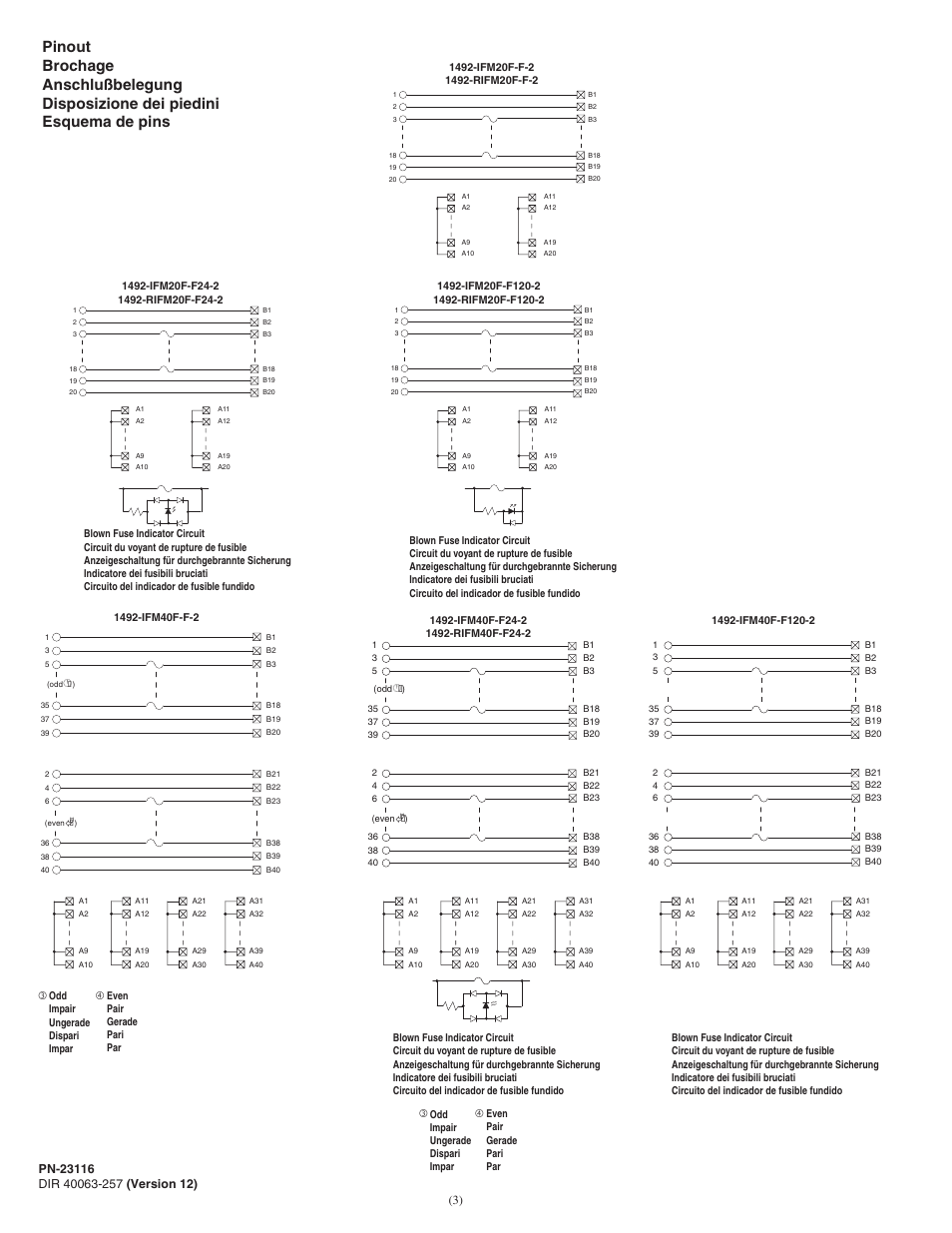
1492-ifm20f-f120a-2 Wiring Diagram
Fusible modules provide a convenient method of adding overcurrent protections into your programmable controller wiring. 1 Adhesive Label Card.
Http Bph Hsph Harvard Edu Datasheets 8ebb3ca2 C7fd 4883 9187 19a4c714b4d9 Pdf
Isolation The power bus is isolated into two groups of 10 terminals.

1492-ifm20f-f120a-2 wiring diagram. Refer to page 186. 1492-ifm20f-f120a-2 1492-rifm20f-f120a-2 1746-ia16 1492-cable a 1746-ib16 1492-cable b 1746-ih16 1492-cable b 1746-in16 1492-cable b 1746-itb16 1492-cable b 1746-oa16 1492-cable c c c 1746-ob16 1492-cable e e 1746-ob16e 1492-cable e e 1746-obp16 1492-cable e e 1746-ov16 1492-cable e e e 1746-ovp16 1492-cable e e e 1746-ow16 1492-cable d d d d. Fusing Fuse holders are included with the IFM.
Fuses 5 x 20 mm are not included. 1492 ifm20f f120a 2 manual DOWNLOAD. 20 mA 4.
Pinout 1492-IFM20F-3 Feed-Through 3-Wire Sensor Type Input. Simplifies design and engineering time. Dimensions Refer to page 187.
Reduces wiring time and wiring errors. Tarjeta de etiquetas adhesivas. Analog AIFM Modules with Field Removable Terminal Blocks RTBs.
Bulletin 1492 wiring system compared with the traditional terminal block method. To obtain the wiring diagram you must select th Pre-Wired Cable Connector selection. Allen-Bradley wiring systems deliver a lower life cycle cost.
Increases machine building productivity. Proporciona identificacin de cableado. Wiring Refer to the Label Section on page 181.
Inches Block Diagram - 18 071 1 7 114 45 5 2 9 8 3 80 315 DIP diagnostic functions. 4 Configure your 1492 cable by filing in the NO SELECTION areas. Scripting must be enabled to use this site.
For Field-Side Wiring Diagrams refer to the Wiring System web site information on page 186. 1492 2 f120a ifm20f manual This topic contains 0 replies has 1 voice and was last updated by lgfqvztcah 1 year 11 months ago. Traditional IO Wiring Assembly Process 023 The assembler begins the arduous task of measuring and cutting each control wire.
1492-IFM20F-F120A-2 1492-RIFM20F-F120A-2 IO Module Module ES EA-Modul Modulo IO Mdulo de ES Cable Matrix Matrice des cbles Kabelmatrix Matrice cavi Matriz de cables. This allows each group of the IO devices to reference a different power source. Bulletin 1492 Programmable Controller Wiring Systems 12-160 Specifications 0 1 2 3 4 5 6 7 8 9 10 11 12 13 Digital IFM Specifications Digital IFM Cat.
These modules have 5 x 20 fuse holders on-board and are available with and without blown fuse indication. Aufklebbare Etiketten zur Kennzeichnung der Klemmenverdrahtung. 5 OUT Z 18V 2 - C C IN Z 18V 1 Wiring Diagram Standards cc 2 5 PS V Out Current Loop 1 I I 6 Wiring Diagram Standards.
For Field-Side Wiring Diagrams refer to the Wiring System web site information on page 186. Wiring Refer to the Label Section on page 181. Fusing Fuse holders are included with the IFM.
Programmable Controller Wiring Systems Voltage V Term. 108 The assembler using the traditional method has measured and cut about 10 of the 18 wires needed for the same job. Extra Terminals Two field-side terminals are internally connected on the IFM for each channel.
Increased Volume and Productivity Cable interconnections for a wiring system can be up to 30 times faster to install than traditional point-to-point wiring enabling OEMs and panel builders using wiring systems to. 20 mA Wiring Diagram 2 Wiring Diagram Standards Compliance UL 6007915 UL 508 EN 60079-02006 EN 60079-152005 CSA C22. Literature Library Rockwell Automation.
120 2 Extra Terminals 1492-IFM20F-FS-2. 10 V Standards Compliance 1 4. Identifie le cblage des bornes.
Supports conversions from 1771 PLC-5 systems to 1756 ControlLogix IO. Benefits from quality-looking panels. 1492-IFM20F-F120A-2 1492-RIFM20F-F120A-2 X Fusible Isolated 24 2 Blown fuse LED 1492-IFM20F-FS24-2 W W W 24.
Provides terminal wiring identification. Fornisce lidentificazione del cablaggio dei terminali. For Field-Side Wiring Diagrams refer to the Wiring System web site information on page 186.
Author Posts 09082019 at 1718 16189 lgfqvztcahParticipant. Per IO Description Fixed Terminal Block Removable. Isolation The power bus fuse clips and blown fuse indicators are isolated into two groups of.
20 mA 0. Supports conversions SLC 500 to CompactLogix 5380 and 5069 Compact IO. EN50020-EN50039 Interface Isolators Galvanic 24V 2A SPST RELAY of 15uF 440k 1492-WD4RA682 EN50020 CSA22 external wiring.
1492-IFM20F-F120A-2 1492-IFM20F-F240-2 1492-IFM20FS-F -2 1492-IFM20FS-F24-2 1492-IFM20FS-F24A-2 For 40-point. Fuses 5 x 20 mm are not included.
Rockwell Automation 1492 Ifmxxx Fusible Interface Modules User Manual Page 3 4
Http Bph Hsph Harvard Edu Datasheets 8ebb3ca2 C7fd 4883 9187 19a4c714b4d9 Pdf
Http Pccomponents Com Datasheets Ab1492h1 Pdf
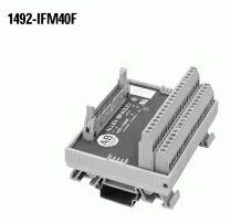
1492ifm40f Ab Allen Bradley 1492 Ifm40f Cbt Company
Http Bph Hsph Harvard Edu Datasheets 8ebb3ca2 C7fd 4883 9187 19a4c714b4d9 Pdf

1492ifm40f Ab Allen Bradley 1492 Ifm40f Cbt Company
Http Bph Hsph Harvard Edu Datasheets 8ebb3ca2 C7fd 4883 9187 19a4c714b4d9 Pdf
Http Bph Hsph Harvard Edu Datasheets Allen Bradley 1492 Ifm20d24 Pdf
Http Bph Hsph Harvard Edu Datasheets 8ebb3ca2 C7fd 4883 9187 19a4c714b4d9 Pdf
1492 Ifm40f Wiring Diagram Programmable Logic Controller Electrical Connector

1492 Ifm40f Wiring Diagram Programmable Logic Controller Electrical Connector

Http Bph Hsph Harvard Edu Datasheets 8ebb3ca2 C7fd 4883 9187 19a4c714b4d9 Pdf
1492 Ifm40f Wiring Diagram Programmable Logic Controller Electrical Connector

Allen Bradley Plc Wiring Systems Electrical Connector Programmable Logic Controller

1492 Ifm40f Wiring Diagram Programmable Logic Controller Electrical Connector


Allen Bradley 1492 Aifm8 F 5 Wiring Module Fusible 5 Term Per 8 Channel Blown Fuse Ind Rexel Usa
1492 Ifm40f Wiring Diagram Programmable Logic Controller Electrical Connector

1492ifm40f Ab Allen Bradley 1492 Ifm40f Cbt Company
Http Bph Hsph Harvard Edu Datasheets 8ebb3ca2 C7fd 4883 9187 19a4c714b4d9 Pdf