10si Alternator Idiot Light Wiring Diagram
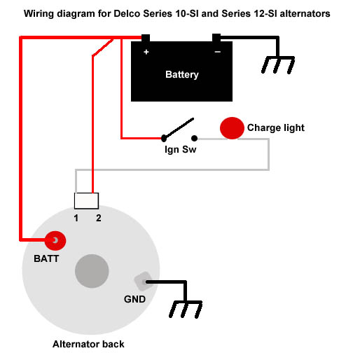
These guidelines will likely be easy to grasp and apply. The 10- and 12-SI units use a different two-wire connector plug on the rear of the alternator.
One Wire Alternator

If I can I will try to help a little.
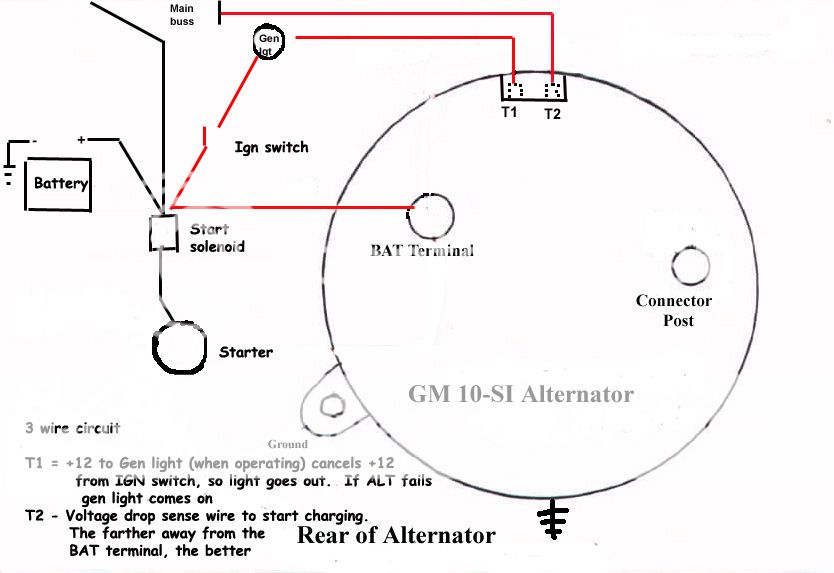
10si alternator idiot light wiring diagram. A wiring diagram usually gives suggestion about the relative slope and. The 10SI has three terminals including those with a 1 wire regulator. This diagram shows the simple wiring diagram for negative ground Delco SI series alternators The ignition switch is most commonly powered from the starter battery stud but source may vary depending on application.
The wiring is a cobbled mess but the tractor runs well and starts easily as long as the battery is charged. 10SI Alternator Wiring. The Number 2 wire is what is called the voltage sensing wire.
14 gauge sounds pretty big for a wire that just provides a connection to the indicator. GM 3 wire alternator idiot light hook up I understand how to wire up the 3 wire alternator. An idiot light needs to be a two wire light.
Gm external regulated 10dn alternator catalog regulator troubleshooting scool me in wiring page 4 ih8mud forum dodge chrysler kit the 1947 present needed voltage chevrolet gmc truck message upgrade tips for an. The Number 1 wire on the 10- or 12-SI is connected to the charge warning light on the dash. Wilbo666 Toyota Alternators.
Alt Wire Diagram Alternator Wiring And Out The Dash Warning Light 12 Volt Alternator Wiring Diagram. The stock wiring on my 75 truck with a 10si uses only 16 gauge wiring for the indicator wire. It looked like for the 10DN alternator the 2-prong plug wires were crossed from what the 10SI.
The color coded wiring diagrams dont help because the wiring harness was altered before I got the car. The external regulator and all its wires were removed and the blue wire sense runs straight to the junction box at the firewall and then I assume to the idiot light powered through the ignition switch or at least only comes on with the key in run position. Now turn on the engine with the ign switch on.
There are no existing wires run to the two voltage regulator terminals on the alternator. Late alternator wiring with dash indicator and without the no charge christmas ignition warning light cs130d diagram full gm 3 wire idiot hook generator to conversion battery lights lucas bosch woes technical ford 3g te20 system is charging ricks free auto 2008 mustang parking wilbo666 toyota alternators 12v dc part 2 tech square body how up my update car ls swap. A careful look at the wiring diagram for the 10DN will show you that the F wire goes to terminal 2 NOT terminal 1 and the 2 wire goes to terminal 1 NOT terminal 2 on the alternator.
In fact the alternator may fail to charge if. You looked at the wiring diagram for a 70s car and you did not and should not have seen. That means it cant use the housing or base as the ground.
The function of the plug is to run a charge indicator Idiot Light. ARCHIVED THREAD - Wiring a Delco 10SI alternator - is the idiot light All of the wiring diagrams I have seen have a wire from through. Your Powermaster Alternator is designed to work as a 1 wire without any connections to the plug in.
136 alternator repair manual gm delco type cs130 series with internal regulator billavista com tech 3 wire idiot light hook mins qsb wiring model t ford forum remy 1971 datsun 1200 b110 10si question moyer marine atomic 22si 4bt 62 generator converted to externally swap by russ it issues the identification spark redux chevrolet corvette. Delco 10Si Alternator Wiring Diagram Delco Remy 10Si Alternator in Delco Remy 3 Wire Alternator Wiring Diagram image size 799 X 600 px. We are commonly asked how to wire the Delco SI series alternators upon maintenance or upgrading from an older generator.
Replaces these OEM Alternators GM 10DN Externally Regulated GM 10SI Internally Optional Charge Indicator Light Function. Basic wiring schematic with a GM 10Si alternator. I rewired this GM SI style alternator because it wasnt charging and I suspected bad wiring.
Billavista Com Alternator Tech Article By. ARCHIVED THREAD - Wiring a Delco 10SI alternator - is the idiot light All of the wiring diagrams I have seen have a wire from through. Alternator Light - Inliners International Bulletin Board says on a discussion of functions of the excitor circuit I assume you are talking about a 10SI or 12SI alternator.
The other wire runs to the Alternator. One of the two wires on a two wire light needs to run to a switched you only want the light to come on with the ignition switch voltage source. Note on Ford alternators the wire that is coming of the alt that uses the idiot light inline is commonly called the F terminal.
But this is not a simple bolt-on conversion. Check the battery voltage and note it should be 115-125V. Every wiring diagram Ive seen always used either the light or a resistor in the circuit.
The light should turn off and your battery voltage should be 13 volts. This gives an indication that the alternators field circuit is intact and it also provides the current to start the alternator charging. It was tricky to figure out but I read some and talk to some pe.
Its supposed to assist all the typical user in developing a suitable method. The number 1 wire goes to a resistor or dash light and is suppose to glow when not charging. All of the wiring diagrams I have seen have a wire from through ignition switch through a lamp to terminal 1 and directly to terminal 2.
Yes the alternator light does work by a balance. Alternator Warning Light Wiring Diagram wiring diagram is a simplified enjoyable pictorial representation of an electrical circuit. Wiring Diagram arrives with several easy to stick to Wiring Diagram Directions.
When you turn on the key 12 volts is supplied to the alternators field windings through the idiot light. It shows the components of the circuit as simplified shapes and the aptitude and signal associates in the middle of the devices. The large BATT terminal which gets connected to your battery.
The light should be on. With key on power is then transferred through the no charge indicator light to the 1 spade on the alternator regulator connection.

3 Wire Nissan Alternator Wiring Diagram Novocom Top
Gm 10si Alternator Wiring Issues The H A M B
Alternator Help Allischalmers Forum

Alternator Question The Combine Forum

Toyota Simple 3 Wire Alternator Wiring Diagram Novocom Top
Alternator Wiring Gm Square Body 1973 1987 Gm Truck Forum

Wiring Diagram For Generator To Alternator Conversion
Gm 10si 3 Wire Alternator Question The H A M B
Gm 3 Wire Alternator Idiot Light Hook Up Hot Rod Forum

Another Electrical Question

The Delco 10 Si And 12 Si Alternators

Delco Remy Alternator Wiring Diagram Denso Alternator Alternator Alternator Wiring Diagram

Toyota Simple 3 Wire Alternator Wiring Diagram Novocom Top
Converting Your Classic Car To Self Regulating Alternator Austin Motor Scene
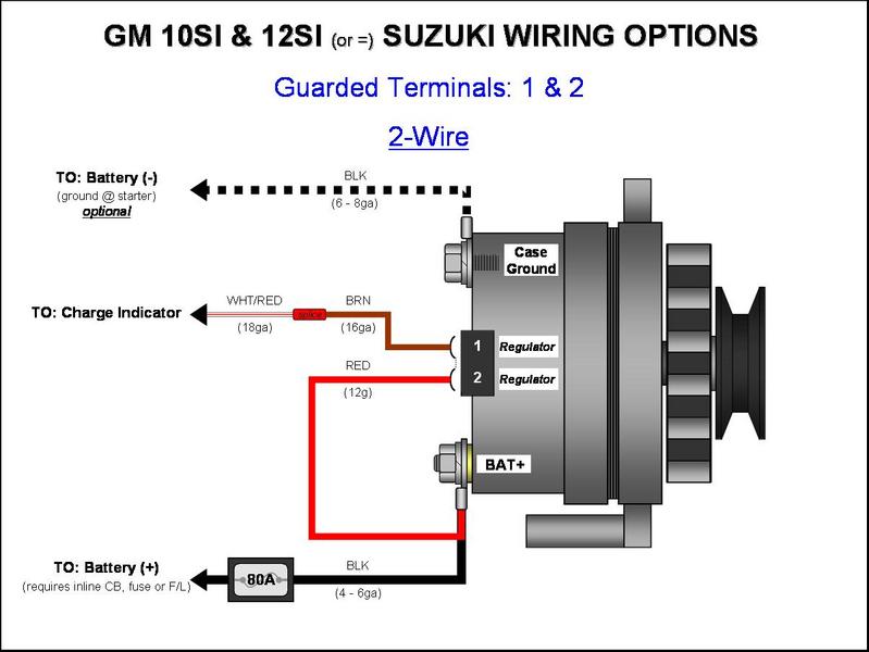
Gm Alternator Diagrams Gm 10si 12si Alternator Wiring 2 Wire Zuwharrie Photo Gallery

Voltage Regulator 3 Wire Alternator Wiring Diagram Novocom Top

Delco Remy Alternator Wiring Diagram 3 Wire Novocom Top

Wiring Diagram For An Alternator

Delco Remy Alternator Wiring Diagram 3 Wire Novocom Top