Floscan Wiring Diagram
FloScan manufactures 12 VDC to 12 VDC PN 7000-097-00 and 24 VDC to 12 VDC. 1 Fuel Flow Transducer Model 201B- 9.
Installing A Fuel Monitor Boating Magazine
You can easily set your boats most efficient speed by watching your FloScan to see how fuel usage varies at different speeds and running conditions.

Floscan wiring diagram. Digiflo PN 91050X. D a b c a - Connect to 12 Volt b - 12 Volt Light Switch Wire c -. Isolated Ground Electrical Systems.
FloScan Instrument Company Inc. 12 to 15 VDC between RED wire and BLACK - wire. Always cover connectors and wire ends with heat shrink tubing.
PN 833811-01 AIS-380 RemoteFlo Fuel Flow Adapter Installation Manual. FloScan Gasoline Lo-Flo system components have Female NPT ports. Click here to view our new installation video which outlines a Series K system installation showing both plumbing and wiring procedures for the standard flow and high flow sensor models.
Most skippers can save 10-15 on their fuel bill so the serious fishermancruise can pay for his FloScan in less than a season. Representing the fuel flow through it. Review the electrical installation instructions.
Tachometers require 1 or 2 additional conductors. It is a good idea to save the back side bracket from your old tachometer as no bracket is included with the FloScan. A FloScan Fuel Computer pays for itself in fuel savings alone.
Digiflo-L PN 91053XT-D. Transducer Power Ground Pulse Output RTD RTD NC Fuel Flow Fuel Flow. Wire TerminationsReferring to the wiring diagram Connect Sensor Instrument and Switches to their respective wires with crimp type butt or ring connectors.
The Floscan 9000-series has a NMEA 0183 input not output and then the Garmin GPSMap 741xs has NMEA 2000 ports. Do not ground the black wire Ground at the engine block. WIRING DIAGRAM A Use this wiring diagram when using a separate light switch for instrument lighting.
Sensor will pull-down to 10 volt with 10-15k ohm pull-up resistor installed. When tightening the AN fittings on the Floscan transducer Shadin PN 68050X the maximum torque pressure to be used is 15ftLbs. Rev 12113 Setting K-Factor - K-Factor is a parameter that is adjusted to calibrate the fuel flow sensor to your installation.
FloScan manufactures 12 VDC to 12 VDC PN 7000-097-00 and 24 VDC to 12 VDC. Failure to follow this suggestion. Yamaha outboard wiring diagram pdf A Beginner s Overview of Circuit Diagrams.
Digiflo PN 91052XT. Receiving from point A to aim B. Literally a circuit is the course that allows electrical power to circulation.
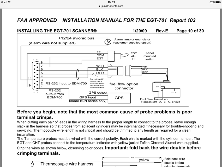
30 to 50 mA at 12 VDC. The wire from pin 4 on the J-1 D-SUB 9 Connector can be connected to an external warning light or buzzer. With wires straight up.
This wire grounds when the display flashes a warning. Carry the Ground back the Shadin fuel flow indicator. To determine the K-Factor compare the actual fuel used to the calculated fuel used on the FC-10.
FF TXD PN 660534HX. The block diagram below in. A first check out a circuit layout may be complicated however if you can check out a metro map you could check out schematics.
Series 700070000 Multi-function Meter. FloScan Gasoline Lo-Flo system components have Female NPT ports. Wire TerminationsReferring to the wiring diagram Connect Sensor Instrument and Switches to their respective wires with crimp type butt or ring connectors.
If theres an existing tachometer its signal wires can be used. Digiflo PN 91051X. Series 5400 AccuTroll 550055000 CruiseMaster.
Isolated Ground Electrical Systems. The current in this line must be limited to 025 amp. Below is a list of the FloscanInc PDF Manuals available for download.
PN 91204XT-38-D Microflo-L OperatingInstallation Manual. Digiflo PN 91052XP. Open collector transistor output on WHITE wire.
Digiflo PN 91052X. Always cover connectors and wire ends with heat shrink tubing. PN 833811-30 AIS-380 RemoteFlo DC Analog Fuel Flow Adapter Installation Manual.
PN 660534HX Hall Effect Fuel Flow Transducer Installation Manual. Open and survey your vessels wire ways and run 3-conductor cables from each sensor to the instrument. This is based on presuming that your Floscan series 9000 is this device.
GAS MODEL INSTALLATION MANUALS. It will be necessary to compare fuel consumption for. Tachometers require 1 or 2 additional conductors.
Review the electrical installation instructions. From here on out it is a simple matter of following the excellent wiring diagram that is included with the instrument. Figure 1 provides an overview of the functional blocks of the transducer.
The new Series K fuel flow sensor design also enhances system performance and accuracy. Route the Optional External Warning Control Line. If theres an existing tachometer its signal wires can be used.
206 523-4961 3016 NE Blakeley Street Seattle WA 98105 Email. Best of all the simplified procedures allow for do-it-yourself installation. To connect one to the other you will need an NMEA 2000 to NMEA 0183 converter such as this one for instance.
Open and survey your vessels wire ways and run 3-conductor cables from each sensor to the instrument. Go slow double check all of your connections and make sure that you arent missing anything.
Boat Project Com Nmea 2000 Fuel Flow System

Boat Project Com Nmea 2000 Fuel Flow System

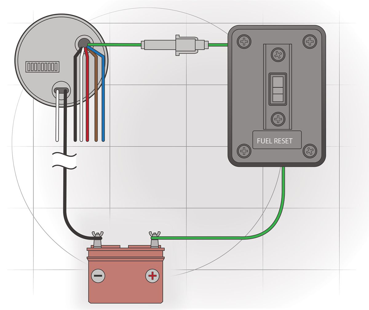
Maintenance Avionics Faulty Indication Of Fuel Remaining Indicator
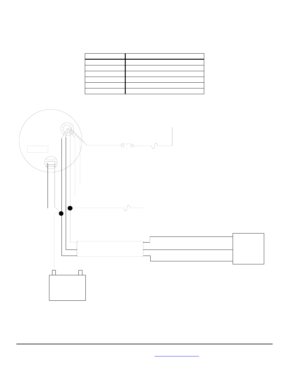
Flow Sensor Battery Wiring Diagram Floscan 5a20 20a 1 Accutroll Cruisemaster User Manual Page 13 22

Flow Sensor Battery Wiring Diagram Floscan 5a20 20a 1 Accutroll Cruisemaster User Manual Page 13 22
Diagram Mark 7 Wiring Diagram Full Version Hd Quality Wiring Diagram Diagramman Prolococusanese It
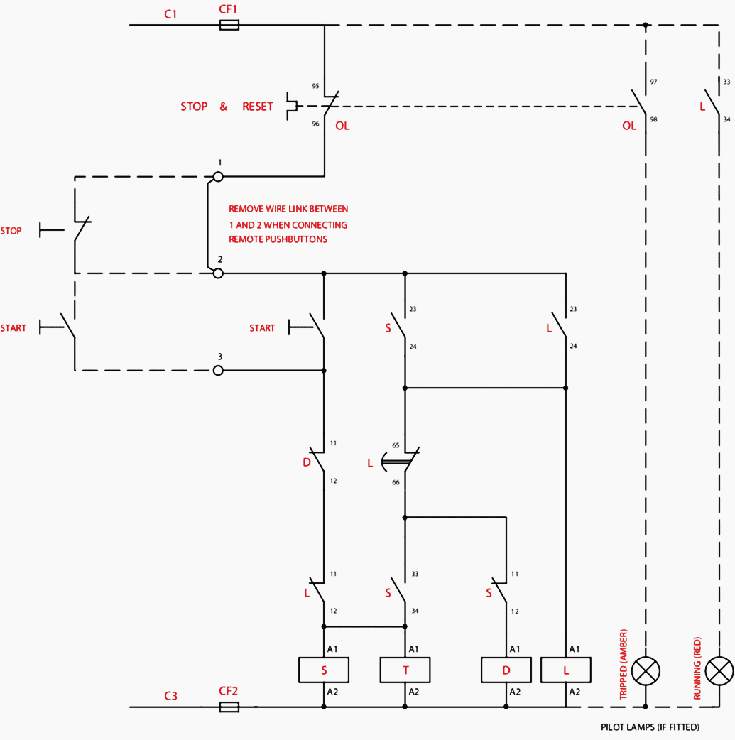
Diagram Star And Delta Control Wiring Diagram Full Version Hd Quality Wiring Diagram Diagramman Prolococusanese It
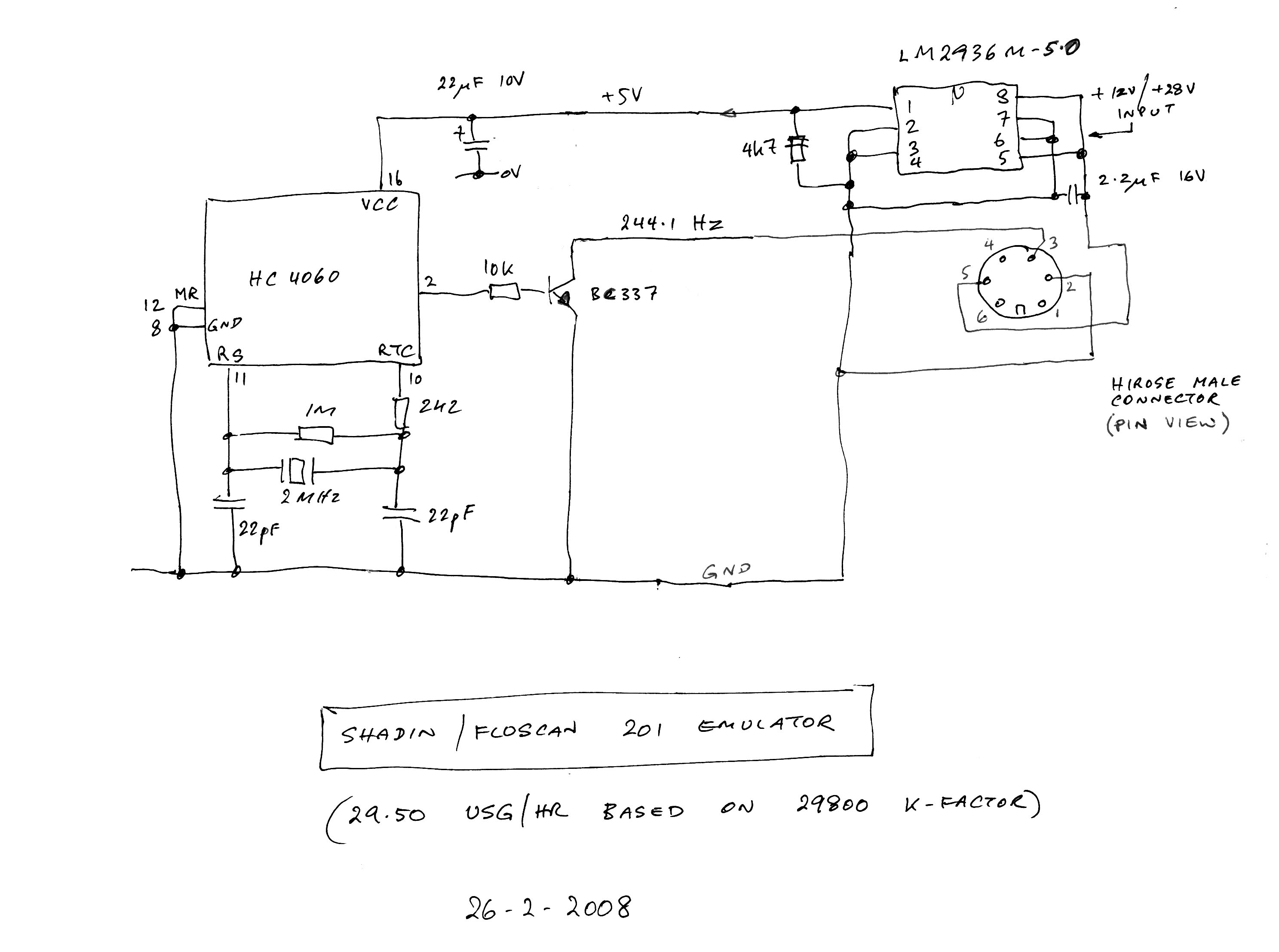
Shadin Flowmeter
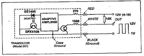
Maintenance Avionics Shadin Floscan 201 Fuel Flow Transducer Internals
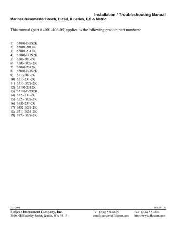
Installation Troubleshooting Manual Manualzz

Floscan Instrument 5510 20b 1 User S Manual Manualzz
Twin Diesel Floscan System
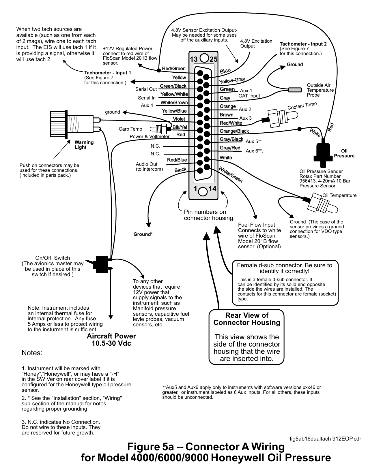
Fig5ab16 Dualtach Eop 912eop Manualzz
Installing A Fuel Monitor Boating Magazine
![]()
Shadin Flowmeter

Floscan Series 5500 Cruisemaster Florida Sportsman
Floscan Instrument Co Inc


Installing A Fuel Monitor Boating Magazine

Diagram Isuzu Ac Wiring Diagrams Full Version Hd Quality Wiring Diagrams Diagramman Prolococusanese It