Derale Fan Wiring Diagram
Positive Battery to Positive Fan Lead Red Fused Harness wire. Please keep in mind that Derale.

Derale 16788 High Amperage Dual Fan Controller Probe For Sale Online Ebay
Derale Fan Relay Diagram 2000 Cavalier Relay Diagram Znlhj.
Derale fan wiring diagram. If fan started reattach the Green wire to the proper wire on the AC clutch or Manual Switch. Wrg 6273 6 6 Duramax Wiring Schematic. Red Wire to the Fan 2 remaining fan positive wire.
Red Wire to the Fan 2 remaining fan positive wire. Diagram Table Fans Wire Diagram Full Version Hd Quality. Using a Yellow Butt Connector and the supplied red wire connect one end of the 10 Ga.
12743 - 8 Pass 17 Dyno Cool Remote Cooler 1132. Derale 16789 Fan Controller Blue Blue Blue Green BlackGreen BlackGreen Yellow Black Red Red Red AC Compressor Clutch Fan 2 Fan 1 Trinary Switch AC Thermostat Switch Or Compressor Relay Gen IV AC Switch Panel Switch On 12V Key-On Ignition Source To Battery 12V AUX BAT Circuit Breaker To Chassis Ground - Harness Side. The Dual Fan Controller and cut the wire to the appropriate length.
Derale adjustable fan controller can be used with Derale or any single or dual fans that draw less than 25 amps total. Black Wire with attached ring. Derale 16795 PWM Fan Controller Blue BlackGreen Blue BlackGreen Blue Blue AC Compressor Clutch Trinary Switch AC Thermostat Switch Or Compressor Relay Gen IV AC Switch Panel Switch On 12V Key-On Ignition Source Yellow 8 Ring Terminal Fans - DERA LE PERFPORMANC E SENSOR OVERRIDE B ATTERY SENSOR FAN BATTERY F NS S A C.
DOWNLOAD G4850 Dual Fans Wiring Diagram Useing Derale 16749 Controller For 1999 Gmc Jimmy 43. Here is a listing of the parts you will need. Run the 10 Ga.
Derale 40 60 Amp Relay. If fan started reattach the Green Wire to the proper wire on the AC clutch or Manual Switch. Trinary Switch Wiring Diagram.
SINGLE FAN CONFIGURATION DUAL FAN CONFIGURATION Orange Wire. Take the supplied Rubber Fan Shroud Seal and install it onto the bottom edge of the Fan Shroud Assembly. TROUBLE SHOOTING QA Diagram 3 Relay Red Yellow Black Green To 12V Switched Ignition To Ground -Chassis Override Circuit Loose Red Wire Positive Battery Negative - Fan Wire Fan.
Derale Adjustable Fan Switch Part 16759 SPST 30 Amp Relay that is Normally Closed. Red Wire connected to the Fan 2 positive lead to the Red Wire furthest from the adjustment screw. Terminal on the battery.
Using a Blue Butt Connector provided attach the Orange wire to the Positive electric fan lead. PATENT 7006762 - MADE IN USA Adjustment Screw Sensor Wire Fan - Fan Override Circuit 12V Electric Calibration Fans Terminal 5. Electric fan should start immediately.
Cut off any excess Rubber. Red Wire connected to the Fan 2 positive lead to the Red Wire furthest from the adjustment screw. Diagram 4 Diagram 2 Chassis Ground - Blue Fan Positive Orange Fan Positive 30Amp Fuse Chassis Ground - Ignition Switch Red 30 86 85 87 Green Orange Diagram 3 Yellow For manual switch wiring refer to.
12741 - 6 Pass 17 Dyno Cool Remote Cooler 1132. To Negative - Electric Fan Lead Black Wire. See Diagram 4 on reverse side Red Loose wire.
Using a table or workbench lay the Electric Fan Assembly on a flat surface Electric Fan facing down. Trinary Switch Wiring Diagram. Cut the wire to the appropriate length.
Wire can be connected in parallel to both Negative - fan leads. Fan 2 Blue Wire. Reference Diagrams 78onpage 2 The Electric Fan Assembly is built using a High Output two speed motor.
G4850 Dual Fans Wiring Diagram Useing Derale 16749 Controller For 1999 Gmc Jimmy 43. Extra Wires match gauge and color to Derale unit Ring connectors for 12-14 and 16-18 gauge wire. Diagram 2 WIRING Before starting disconnect the Negative - cable on the vehicles battery.
Using a Yellow Butt Connector and the supplied red wire connect one end of the 10 Ga. The electric fan should start immediately. Connect wires using one of the supplied Yellow Butt Connectors.
Wiring diagram for 99 gmc jimmy blower motor - GMC Jimmy question. If you choose to operate the fan using both speeds two switching devices or a Derale Dual Fan Controller Part 16788 or 16789 is recommended. 12740 - 6 Pass 13 Dyno Cool Remote Cooler 1132.
Electric fan conversion on chevy truck. Connect wires using one of the supplied Yellow Butt Connectors. 12901 - 4 Pass 13 Dyno Cool Series 6000 Aluminum Transmission Cooler.
Diagram 4 DERALE PERFPORMANCE SENSOR OVERRIDE Y SENSOR N Y ION R ER N S S A C US. SPDT 30 amp switch. Cut the wire to the appropriate length.
2002 Jeep Fan Control Wiring Wiring Diagram Tri. If fan started reattach the Green Wire to the proper wire on the AC clutch or Manual Switch. 12742 - 8 Pass 13 Dyno Cool Remote Cooler 1132.
Using the Blue 10 Ring Terminal provided attach the black wire to a good chassis ground. Fan 1 Orange Wire. Derale Controller Countour Fan Wiring Help Needed Vintage.
See Diagram 4 3. Route the Red 10 wire now connected to the auxiliary side of the circuit breaker to the Positive Battery Terminal on theAWG. The Derale High Amperage Adjustable Dual Fan Controller is designed to operate two electric fans at different activating temperatures.
Dual 14 Inch Electric Fan W Derale Thermostat Sensor. Run the 10 Ga. ORANGE Wire - Attach to a 30 Amp fused Circuit Fuse not included after the fuse connection attach to the Positive Electric Fan Lead Fan YELLOW Wire - Attach to 12V Switched Power Thermostat or Manual Switch GREEN Wire - OPTIONAL Attach to the Positive feed from the AC Clutch This wire will allow you to turn on the Electric Fan every time.

Derale Performance High Amperage Adjustable Dual Electric Fan Controller Push In Probe User Manual 2 Pages

Cherokee Electric Fan Derale Thermostat Cherokee Electric Fan Derale Thermostat
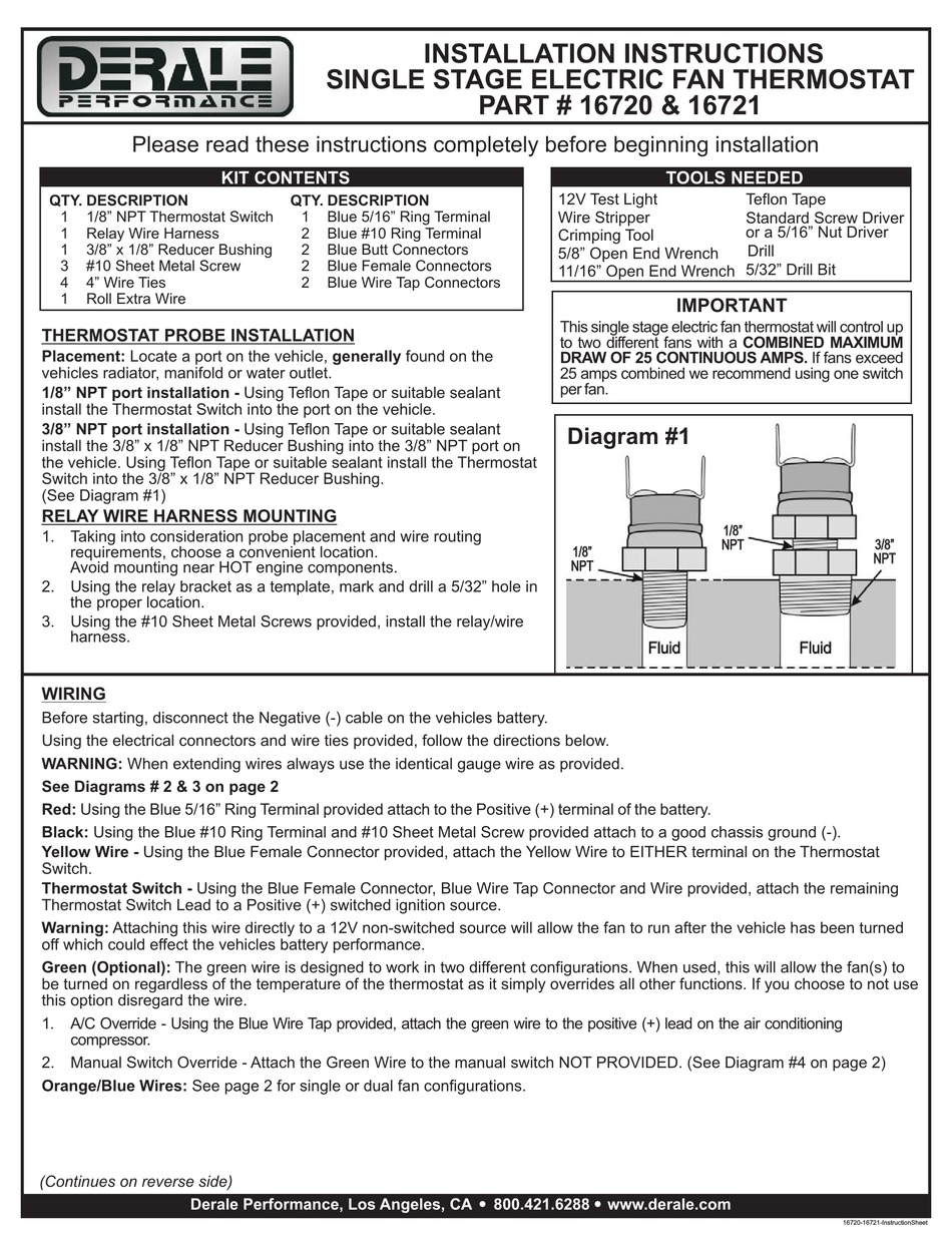
Derale 16720 Installation Instructions Pdf Download Manualslib
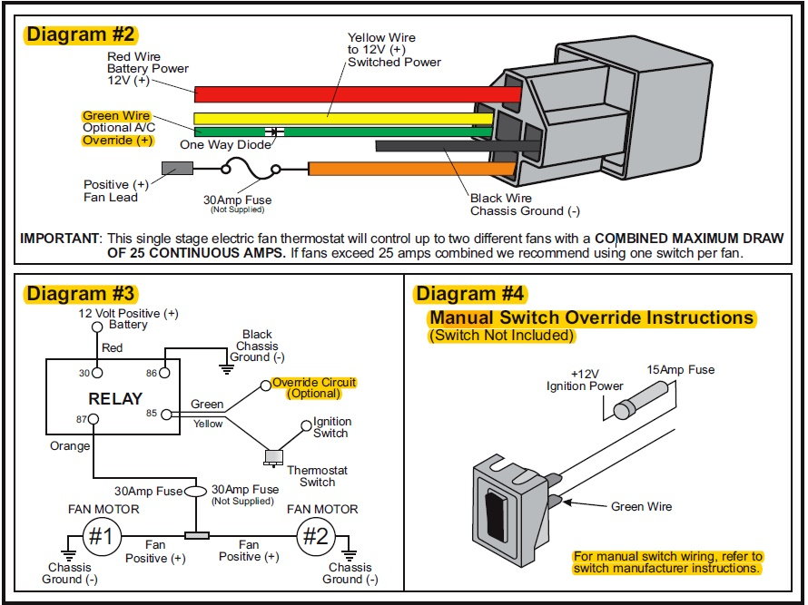
Need A Source For Troyer S E Fan Controller F150online Forums
Diagram Spal Fan Controller Wiring Diagram Full Version Hd Quality Wiring Diagram Diagramman Prolococusanese It

Derale 16789 High Amperage Dual Fan Controller With 3 8 Npt Thread In Probe Engine Cooling Fans Parts Wellbeam Com
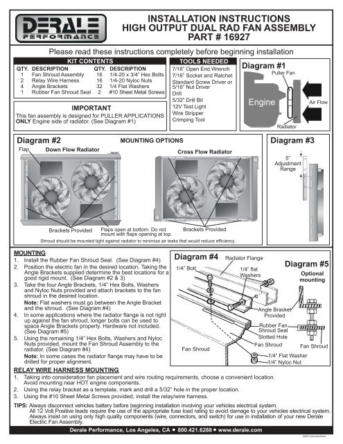
Installation Instructions High Output Dual Rad Fan Assembly Part Jegs
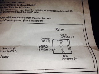
Make Sure Im Wiring These Derale 16925 Pushers Correct Pics Ls1tech Camaro And Firebird Forum Discussion
Derale Controller Countour Fan Wiring Help Needed Vintage Mustang Forums

Derale Controller Wiring Diagram For Installing A Derale F Flickr
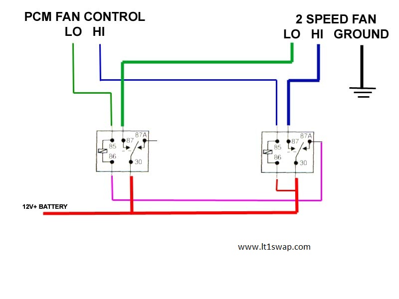
Derale 16925 Fan Wiring Ls1tech Camaro And Firebird Forum Discussion
Dual Electric Fan Wiring The 1947 Present Chevrolet Gmc Truck Message Board Network

16795 Derale Performance Universal Pwm Fan Controller Manualzz

Derale Performance Electric Fan User Manual 1 Page

Diagram Derale Relay Wiring Diagram Full Version Hd Quality Wiring Diagram Diagramman Prolococusanese It
Derale Fan Controller Wiring Diagram Mphmshelby
Derale 16579 Has Been Redesigned No Longer A Positive Switching Circuit Third Generation F Body Message Boards
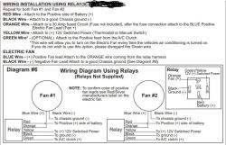
How To Wire The Derale 26 Dual Electric Radiator Fan Part D16927 To A Manual Switch Etrailer Com
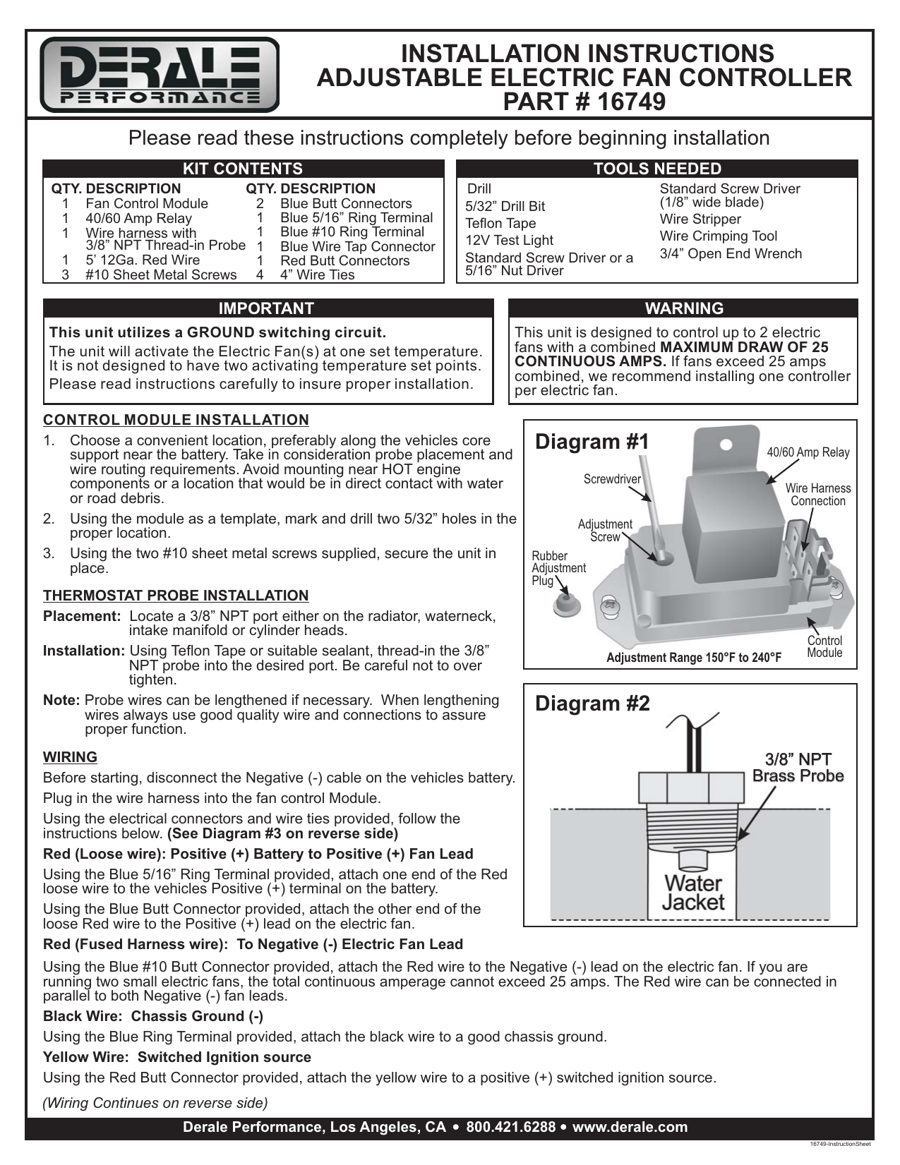
Installation Instructions Adjustable Electric Fan Controller Manualzz