08 Colorado Air Pump Solenoid Wiring Diagram
The Secondary Air Injection AIR System aids in the reduction of hydrocarbon exhaust emissions during a cold start-up. This occurs when the start-up engine coolant temperature ECT is between 5-50C 41-122F and the intake air temperature IAT is between 5-60C 41-140F.

Diagram Light Relay Wiring Diagram Full Version Hd Quality Wiring Diagram Diagramman Prolococusanese It
Here you will find fuse box diagrams of Chevrolet Colorado 2004 2005 2006 2007 2008 2009 2010 2011 and 2012 get information about the location of the fuse panels inside the car and learn about the assignment of each fuse fuse layout and relay.

08 colorado air pump solenoid wiring diagram. Power Windows Page A-2 3. Clock Cig Lighter Page A-5 6. P2432 CHEVROLET Description.
The sensor is a 3-wire sensor that measures the AIR system pressure at the AIR control solenoid valvepressure sensor assembly inlet. The AIR solenoid relay supplies the current needed to operate the AIR control solenoid valvepressure sensor assembly. Ignition Coil 20 Ampere Fuse 16.
Wheel Revolutions - Left Rear. The Secondary Air Injection AIR System aids in the reduction of hydrocarbon exhaust emissions during a cold start-up. Wheel Revolutions - Left Front.
The AIR pump relay-The AIR pump relay supplies high current and battery voltage to the AIR pump. CIRCUIT FUNCTIONS All circuits in the diagrams use an alphanumeric code to identify the wire and its function. If the AIR solenoid does not activate test the controlled output circuit for an openhigh resistance.
Power Mirrors Page A-3 4. Raise vehicle on hoist. The engine control module ECM supplies the internal pressure sensor with a 5-volt reference an electrical ground and a signal circuit.
Wiring Diagram and Installation Notes. We ran our lines back underneath the compressor bracket. Door Locks Page A-4 5.
Finish up the install by running your solenoid air line and switch clips back along with the firewall electrical lines. WIRING HARNESS CONFIGURATION DIAGRAMS Connector symbol 01 thru B 37 C-6 DASH PANEL B-01 2-R Passenger seat air bag module squib B-02 2 Heater water temperature sensor air conditioner B-03 2-B Air thermo sensor air conditioner B-04 20-B AC-ECU. Throttle Position Sensor TPS 12.
FOR THE CREW CAB. Gray - Front RIGHT Door. The AIR pump operates 5-60 seconds after.
Connect a 15A fused jumper wire between the AIR solenoid relay switch B circuit terminal 30 and the controlled output circuit terminal 87. Replace the AIR pump and install a new inlet hose and solenoid tube assembly using the following procedure. Dark Green - Back Doors.
Block Pressure Sensor 8. In this article we consider the first-generation Chevrolet Colorado produced from 2004 to 2012. Headlights Page L-1 2.
Electric Fuel Pump 20 Ampere Fuse 15. Air solenoid 4way pack p. Remove AIR pump inlet hose.
Low Oil Switch 18. If the circuit tests normal test or replace the AIR solenoid. Disconnect electrical connectors from pump and solenoid.
Air Temperature Sensor 11. Other wiring problems look in links below in my signature they have many links to fuse and wiring for Newmar coachs with wiring diagrams. If there is a leak in the injection system then the pump will not build enough pressure.
This occurs when the start-up engine coolant temperature ECT is between 5-50C 41-122F and the intake air temperature IAT is between 5-60C 41-140F. You can see one red arrow on the left-hand side of the image. A pressure sensor is used to monitor the air flow from the AIR pump.
14103 remote power units solenoid packs remote engine speed controller p. After making numerous calls to dealers I finally found information on the SPEAKER wiring diagram for the Colorado Crew Cab. Verify the AIR solenoid is activated.
AND SHALL NOT BE USED OR. The AIR pump operates 5-60 seconds after start-up. Understanding Diagrams Page U-1 Lighting Systems 1.
ECM DriverOil Pump Circuit 20 Ampere Fuse 14. Stop Lights Page L-3 4. The Data Link Connectors wiring diagrams show the circuits by which the various on-board computers exchange information and the diagnostic connectors used for diagnosis and their location.
To identify which circuit code applies to a system refer to the Circuit Identification Code Chart. Remove shield covering AIR pump. The Secondary Air Injection AIR System aids in the reduction of hydrocarbon exhaust emissions during a cold start-up.
This occurs when the start-up engine coolant temperature ECT is between 5-50C 41-122F and the intake air temperature IAT is between 5-60C 41-140F. The PCM commands the relay ON by supplying a ground to the relay control circuit. You can unplug the fuel quantity solenoid on the CP3 pump and the pressure should default to maximum 23500 PSI however during the first 30 seconds during starting the fuel quantity solenoid is inactive.
Crank Position Sensor 13. They are as follows. Automatic Light Turn-off Page L-4 5.
Turnsignals Hazard Page L-2 3. The Ground Distribution wiring diagrams show all vehicle ground points their location and the components common to those ground points. Remove hose and vacuum lines from pump and solenoid.
Accessories 20 Ampere Fuse 17. Each wire shown in the diagrams contains a code which identifies the main circuit part of the main circuit gage of wire and color Fig. Yellow - Apparently in some models the RIGHT REAR door has blue wires.
This is where we zip-tied our solenoid air line down to our twin compressor wiring harness. Daytime Running Lights Page L-5 Accessories Systems 1. Rear Window Defogger Page A-1 2.
The AIR pump operates 5-60 seconds.
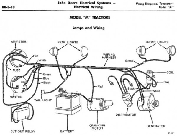
Diagram Wiring Diagram Jd Mt Full Version Hd Quality Jd Mt Diagrammar Prolococusanese It

Diagram 801 Ford Solenoid Diagram Full Version Hd Quality Solenoid Diagram Ppcdiagram Amicideidisabilionlus It
Diagram Wire Diagram Starter Full Version Hd Quality Diagram Starter Diagramap Teatrodelloppresso It


Hydraulic Solenoid Valve Wiring Diagram Volovets Info Wiring Diagram Diagram Hydraulic Systems

Toyota Alternator Wiring Diagram Plus Graphic Toyota Hilux 12v Relay Wiring Diagram 5 Pin Diagram Relay Diagram Design Wir Alternator Toyota Corolla Toyota
Diagram 4 Pole Starter Solenoid Wiring Diagram Full Version Hd Quality Wiring Diagram Imdiagram Amicideidisabilionlus It
Diagram Superwinch Uni1503 Solenoid Wiring Diagram Full Version Hd Quality Wiring Diagram Diagramman Prolococusanese It

Diagram Solenoid Valvecar Wiring Diagram Full Version Hd Quality Wiring Diagram Diagramman Prolococusanese It

Diagram Western Unimount Plow Solenoid Wiring Diagram Full Version Hd Quality Wiring Diagram Trudiagram Amicideidisabilionlus It

Diagram 3 Terminal Solenoid Wiring Diagram Full Version Hd Quality Wiring Diagram Imdiagram Amicideidisabilionlus It
Diagram Circuit Diagram 12v Starter Solenoid Full Version Hd Quality Starter Solenoid Veediagram Amicideidisabilionlus It

Diagram 12 Volt Starter Switch Wiring Diagram Full Version Hd Quality Wiring Diagram Imdiagram Giardinowow It

Diagram Yamaha Atv Winch Solenoid Wiring Diagram Full Version Hd Quality Wiring Diagram Trudiagram Amicideidisabilionlus It
![]()
Diagram 208v Pump Wiring Diagram Full Version Hd Quality Wiring Diagram Diagramhs Segretariatosocialelatina It

Diagram 4l60 Tcc Solenoid Wiring Diagram Wire 2 Full Version Hd Quality Wire 2 Imdiagram Amicideidisabilionlus It

Diagram Gas Ezgo Wiring Diagram Full Version Hd Quality Wiring Diagram Snadiagram Segretariatosocialelatina It

Diagram Ac Wiring Diagram Isuzu Full Version Hd Quality Diagram Isuzu Diagrammoi Prolococusanese It

Diagram Wiring Diagram For A Starter Relay Full Version Hd Quality Starter Relay Trudiagram Amicideidisabilionlus It
Diagram Ford 4wd Wiring Diagram Full Version Hd Quality Wiring Diagram Cpudiagram Segretariatosocialelatina It